
What Makes a Kernel Fast#
Overview
The roofline model gives a kernel a performance ceiling from memory bandwidth and compute throughput, while arithmetic intensity decides which ceiling applies.
Low arithmetic intensity usually means memory-bound: performance is mainly limited by memory bandwidth. The optimization focus is to reduce HBM traffic, improve reuse, fuse operations, and get as close as possible to the memory-bandwidth roof.
High arithmetic intensity usually means compute-bound: performance is mainly limited by compute throughput. The optimization focus is to keep Tensor Cores busy and reduce idle time on the compute path through overlap.
A kernel is only fast relative to a ceiling. A number like 330 TFLOP/s may look large by itself, but it means something very different on a GPU that can sustain on the order of 2 PFLOP/s on dense fp16 or bf16 Tensor Core work. Without a ceiling, it is hard to tell whether a kernel is close to the hardware limit or still leaving most of the chip idle.
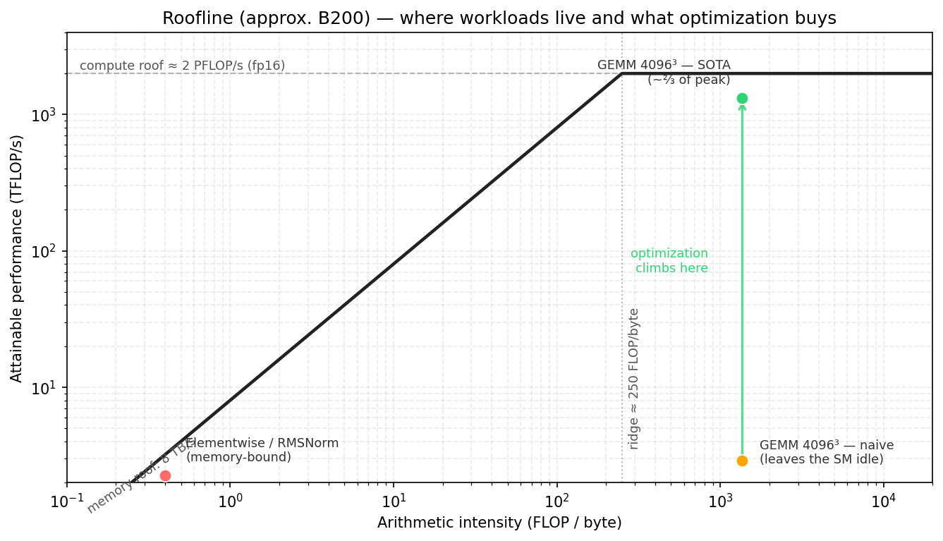
This chapter uses the roofline model to establish that reference point, with NVIDIA B200 as a concrete example. We use two rounded values for calculation: roughly 2 PFLOP/s of dense fp16 or bf16 Tensor Core throughput and 8 TB/s of HBM3e bandwidth. Actual performance also depends on the device configuration, clock rate, power limit, and measurement environment, so these numbers are convenient approximations rather than exact specification limits.
The Roofline Model#
From a performance-analysis perspective, a kernel spends its time on two main activities: moving data and doing arithmetic. The roofline model gives a simple way to reason about this: the kernel’s performance ceiling is jointly determined by the compute-throughput ceiling and the memory-bandwidth ceiling, and more specifically by the lower of the two.
The compute ceiling, or peak compute throughput, is the maximum FLOP/s the hardware can provide on the compute path used by the current kernel. For dense FP16/BF16 Tensor Core GEMM on B200, this ceiling usually comes from Tensor Core throughput. For scalar or elementwise kernels, it may instead come from CUDA cores, special-function units, or some other execution unit.
Memory bandwidth is the amount of data that a memory level can transfer per unit time, usually measured in GB/s or TB/s. The 8 TB/s value above means that, under ideal conditions, the HBM interface can transfer about 8 TB of data per second. A bandwidth number therefore always refers to a particular level of the memory hierarchy: HBM, L2, and shared memory have different bandwidths. Unless stated otherwise, this chapter uses memory bandwidth to mean HBM bandwidth.
Given this bandwidth ceiling, the memory-side performance ceiling can be estimated by multiplying HBM bandwidth by arithmetic intensity. If a kernel does little computation for each byte moved, its performance is usually limited by HBM bandwidth. If each byte supports many operations, the kernel has a better chance of entering the compute-bound region, where the ceiling is more likely to be set by compute throughput.
In units of FLOP/s, the basic roofline bound is:
Arithmetic intensity is:
Here, compute work means the mathematical operations required by the algorithm, usually measured in
FLOPs, rather than the total number of instructions executed by the kernel. By convention, one
floating-point addition or multiplication counts as 1 FLOP, while one fused multiply-add,
a * b + c, counts as 2 FLOPs.
For GEMM C = A @ B, if A has shape M × K and B has shape K × N, the compute work is
usually written as:
The memory level must be specified. For an HBM roofline, the bytes are HBM bytes. For an L2 roofline, they are L2 bytes. For an SMEM roofline, they are shared memory bytes. In this chapter, the default roofline is the HBM roofline.
On a roofline plot, the x axis is arithmetic intensity, measured in FLOP/byte. The y axis is the performance the kernel can reach. The memory-bandwidth ceiling is a sloped line:
The compute-throughput ceiling is a horizontal line:
The point where this horizontal line intersects the memory-bandwidth line is called the ridge point, the boundary between memory-bound and compute-bound behavior:
Using the B200 round numbers from this chapter, the ridge point has units of FLOP/byte:
In this rough model, classify a kernel by comparing its arithmetic intensity with the ridge point:
Below the ridge point: the memory-bandwidth line sets the roof, so the kernel is more likely memory-bound.
Above the ridge point: the compute-throughput line sets the roof, so the kernel is more likely compute-bound.
Near the ridge point: the two ceilings are similar, so either resource may matter.
This comparison is an initial classification rather than a substitute for measurement and profiling. It still gives the optimization direction: reducing a few arithmetic instructions rarely helps a memory-bound kernel, while a small memory optimization does not change the primary bottleneck of a compute-bound kernel.
Arithmetic Intensity of Common Workloads#
Arithmetic intensity first depends on how the algorithm reuses data. We can therefore often make an initial prediction about the bottleneck before writing the kernel.
Elementwise and Reductions#
Elementwise kernels such as GELU and reduction kernels such as RMSNorm usually read and write large tensors while performing relatively little computation per element. Their arithmetic intensity is therefore low, placing them to the left of the ridge point, where performance is primarily limited by memory bandwidth.
GEMM#
GEMM is the opposite case. Its arithmetic intensity grows with problem size because each loaded tile can be reused for many multiply-accumulate operations.
For a square fp16 matmul with M = N = K, the ideal arithmetic intensity (AI) is approximately:
The unit is FLOP/byte. This estimate assumes that A and B are each read from HBM once, C is written
once, and beta = 0, so the old C does not need to be read. It also assumes perfect on-chip reuse
with no extra metadata, padding, or redundant traffic. Metadata includes auxiliary values such as
the scales used by low-precision formats. Real kernels usually move more data, but this estimate is
still useful for understanding the overall trend.
Attention#
Attention sits between these extremes. Its arithmetic intensity depends on sequence length, head dimension, tiling, masking, and whether intermediate tensors are materialized.
One major performance cost in standard attention is the score matrix produced by QK^T. Writing
this intermediate to HBM and reading it back creates a large amount of memory traffic. Flash
Attention, including Flash Attention 4, keeps the relevant tiles on chip and avoids that round trip,
thereby increasing arithmetic intensity.
Attention optimization therefore operates at two levels. At the algorithm level, it reduces HBM traffic and raises arithmetic intensity. At the implementation level, it schedules the remaining data movement and computation to overlap as much as possible.
Optimizing Memory-Bound Kernels#
Once a kernel is known to be memory-bound, there are two avenues for optimization: reduce HBM traffic to raise arithmetic intensity, or, when the traffic cannot be reduced further, bring the actual data-transfer rate as close as possible to the bandwidth ceiling.
Fusion is often the most direct method. A common source of low arithmetic intensity is an intermediate tensor that one kernel writes to HBM and the next operation immediately reads back. Fusing the operation that produces the intermediate with the operation that consumes it can keep the value in registers or on-chip storage such as SMEM or TMEM, avoiding the HBM round trip.
Fuse GEMM with an elementwise epilogue.
Fuse normalization into an adjacent operator.
Compute attention without materializing the full score matrix.
Another approach is to increase reuse through tiling, also called blocking in this context. Tiling divides a large problem into smaller tiles so that data loaded on chip can be used multiple times. In GEMM, one A element contributes to many C elements in the same row, while one B element contributes to many C elements in the same column. Reloading those values from HBM for every use would create substantial traffic.
Keeping A and B tiles on chip allows the same 2MNK operations to use fewer HBM bytes, increasing
arithmetic intensity. The same principle applies to other workloads that repeatedly reuse a tile.
The following simplified model makes this reuse explicit. Suppose one CTA computes a
B_M × B_N tile of C. Each K-stage loads a B_M × B_K tile of A and a B_K × B_N tile of B,
and each element occupies s bytes. Counting only the A/B global-memory traffic for this stage and
ignoring reads and writes of C, the arithmetic intensity is approximately:
If B_M = B_N = B, this becomes:
For a concrete example, keep the overall GEMM dimensions M, N, and K fixed, so the total
computation remains 2MNK. We compare only the on-chip reuse produced by different CTA tile sizes.
Suppose the dtype is FP16/BF16, so s = 2 bytes, and each K-stage uses B_K = 64. With a
16 × 16 CTA tile, the work in one stage is:
The A/B data read from global memory is:
The A/B arithmetic intensity for this stage is therefore
32768 / 4096 = 8 FLOP/byte. If the CTA tile grows to 64 × 64 while B_K = 64 remains fixed,
the computation becomes:
and the A/B data read becomes:
The arithmetic intensity becomes 524288 / 16384 = 32 FLOP/byte. A larger tile lets each A/B
element loaded from global memory participate in more on-chip computation, reducing the amount of
data movement required for the same amount of work.
Real kernels must also account for reads and writes of C, L2 reuse, occupancy, register pressure, SMEM bandwidth, Tensor Core issue rate, and other factors. Although simplified, this model captures why tiling raises arithmetic intensity: an A or B element loaded from global memory can serve more multiply-accumulate operations inside the tile.
Another way to raise arithmetic intensity is to use a smaller dtype. Moving from fp32 to fp16, fp8, or fp4 reduces data movement and increases useful work per byte. If a low-precision format requires extra metadata, scale factors, or conversions, the actual gain will be smaller than dtype size alone suggests. Scale factors are auxiliary values used to recover the numerical range of low-precision data; block-scaled fp8 and fp4 require such values. Even so, smaller dtypes remain a direct way to increase arithmetic intensity.
When arithmetic intensity cannot be raised further, the optimization target shifts to effective bandwidth. Pure copies, simple elementwise operations, and single-pass reductions over large tensors usually offer neither useful intermediates to fuse nor enough data reuse to exploit. In that case:
Move each byte only once and avoid redundant reads.
Use coalesced or vectorized accesses.
Use TMA for regular bulk tiles.
Keep enough memory requests in flight to prevent the memory pipeline from going idle.
Once a memory-bound kernel reaches the memory roof, further compute optimization does not help. The only way to go faster is to change the algorithm so it moves fewer bytes.
The Optimization Ladder#
The roofline model identifies a kernel’s performance ceiling, but it does not tell us how to build an implementation that approaches that ceiling.
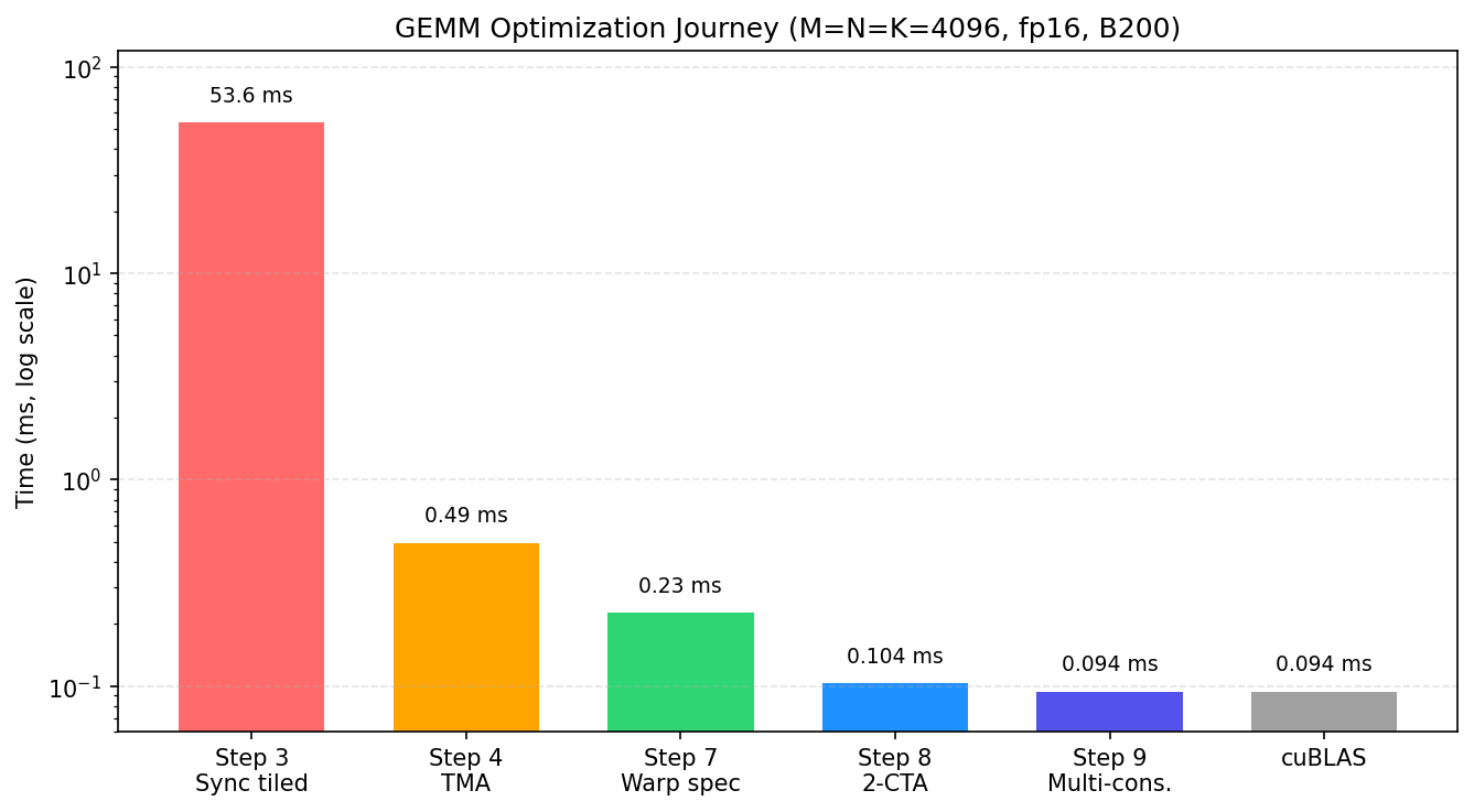
A large fp16 GEMM may be compute-bound in theory. That only means the HBM-level memory roof is not the main limit; it does not mean any implementation will reach the Tensor Core compute roof. Closing the gap requires the right instructions, layouts, staging, synchronization, and scheduling. The later GEMM chapters show this on B200 through a sequence of steps: each step keeps the same basic algorithm but changes how the tile is computed or scheduled.
In the GEMM optimization ladder, the first large measured jump is the move from the thread-copy tiled path to the TMA-backed path. The former uses ordinary CTA threads to copy tiles from GMEM to SMEM; the latter delegates this regular tile movement to the TMA hardware engine. TMA fills SMEM through hardware-managed bulk copies, and the MMA path then reads those tiles from SMEM.
After that first jump, subsequent optimizations address one question: how can the kernel reduce waiting among data movement, Tensor Core computation, and the epilogue? Software pipelining and warp specialization rearrange these stages so that different hardware units can work concurrently. The next section examines this scheduling strategy.
Some structural changes do not improve performance immediately. Warp specialization, for example, may temporarily increase resource use, but it provides the structure needed for more sophisticated overlap later.
The figure below previews the optimization path developed in the GEMM chapters. Each point corresponds to an implementation structure; later sections explain what TMA, warp specialization, CTA clusters, and multi-consumer execution each change.
Reducing Idle Time Through Overlap#
Once a GEMM is compute-bound and already uses Tensor Cores, the remaining gap usually reflects periods when one or more execution paths are not fully utilized.
A simple kernel might do this:
load tile k
compute tile k
store tile k
load tile k + 1
compute tile k + 1
store tile k + 1
This schedule leaves the hardware units idle in turn. The Tensor Core may wait during a load; the copy engine may sit idle during computation; and both may wait while a store drains.
A pipelined kernel instead tries to run independent stages together:
load tile k + 1
compute tile k
store tile k - 1
On Blackwell, TMA, tcgen05.mma, and the epilogue/store path primarily execute these three stages,
while mbarrier coordinates completion and buffer ownership between them.
Overlap does not remove dependencies. The MMA for tile k must still wait for that tile to load, and
the epilogue must still wait for the MMA to complete. The kernel can instead advance independent
work, such as loading tile k+1 or writing back tile k-1.
Occupancy and Resource Pressure#
Besides overlap, GPUs can also hide latency by increasing SM occupancy.
SM occupancy describes how much work can reside on one SM at a time. When one warp stalls, the scheduler can run another ready warp and thereby hide the latency.
Registers, shared memory, warp slots, and CTA slots limit SM occupancy. Warp slots and CTA slots set the maximum number of warps and CTAs that can reside on an SM. If each thread uses many registers or each CTA uses a large amount of shared memory, fewer CTAs or warps fit on the SM and occupancy falls.
Many modern Tensor Core kernels intentionally spend resources in ways that reduce occupancy. Multi-stage shared memory pipelines consume SMEM. Large register fragments consume registers. TMEM allocations consume Tensor Memory capacity. Warp specialization may reserve whole warps for producer or consumer roles.
This is a deliberate tradeoff. Rather than hiding latency with many resident warps, these kernels explicitly overlap stages within a smaller number of resident CTAs. A low-occupancy kernel may still perform well if its pipeline keeps TMA, Tensor Cores, and the store path active.
Each approach has its place. Kernels with irregular memory access or limited opportunities for an explicit pipeline often rely more heavily on high occupancy. Kernels with deep staging and warp specialization may trade occupancy for greater overlap. Occupancy alone is therefore not a measure of quality; the important question is whether the critical hardware units remain active.
Using Roofline to Guide Optimization#
A practical kernel analysis can proceed in three steps:
Estimate arithmetic intensity: how much computation is performed for each byte moved?
Compare that intensity with the roofline ridge point to determine whether memory bandwidth or compute throughput is the more likely limit.
Measure how far the implementation is from the relevant roof, then optimize the resource that is actually binding.
For a memory-bound kernel, focus on reducing data movement and making transfers approach the bandwidth ceiling. For a compute-bound kernel, focus on reducing idle time in the compute units. The roofline model does not produce the final implementation, but it prevents effort from being spent on resources that are not the bottleneck.
Roofline interpretation starts from a trustworthy measurement. The practical workflow for timing a kernel, locating its expensive launches with Proton, and testing a hardware hypothesis with Nsight Compute is collected in Measuring and Analyzing GPU Kernel Performance.